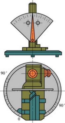
1. The structure and use of universal tool knives The tool angle table shown in Fig. 1 can conveniently measure the turning tool geometry. It is mainly composed of a base, a column, a measuring table, a positioning block, a size dial, a size indexing chip, a nut, and the like. The base and the column are the main body supporting the entire structure. The tool is placed on the measuring stand, and the positioning block can be rotated together with the measuring stand in a clockwise or counterclockwise direction, and can be moved left and right along the positioning block on the measuring stand. Rotating the large nut allows the slider to move up and down so that the two dials and indexer are at the desired height. In use, the angle of the measured angle can be read from the base or dial by rotating the measuring table or the front or bottom surface or side of the large index plate and the measuring element of the tool is in close contact with the measuring element. Figure 1 Universal Tool Knife Angle Table 1-Measurement Stage 2 - Positioning Block 3 - Fingerprint 4 - Slide 5 - Post 6 - Small Finger 7 - Bending 8- Small Scale Plate 9- Knob 10- Large Scale Plate 11- Large Nut 12- Large Finger Plate 13- Base 2. Measure the geometric angle of the outer turning tool (1) Adjustment of original position All the index plates and measuring tables of the angle table are adjusted to zero position, and the tool is placed on the measuring table so that the turning tool is closely attached to the positioning block and the tool tip is tightly attached to the large finger film. Big face. At this time, the bottom surface of the large index piece is parallel to the base surface, and the axis of the arbor is perpendicular to the large surface of the large index piece, as shown in FIG. 2 . Figure 2 Original Position Adjustment (2) on the base surface Figure 3 on the base (3) in the cutting plane Figure 4 in the cutting plane (4) In the main section Figure 5 in the main section You can read the front corner on a large scale Figure 6 in the main section Metal 3D Printer,Ceramic Sand Casting Molds,Advanced Metal 3D Printer,Compact Binder Jet 3D Printer Guangdong Fenghua Zhuoli Technology Co., Ltd , https://www.fhzl3d-print.com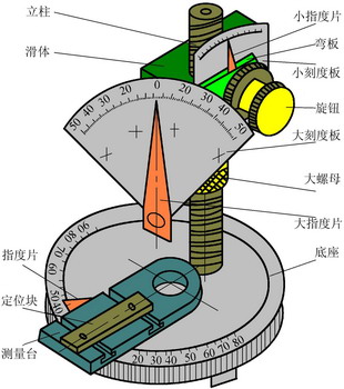
 Measure the leading angle
  Declination angle
  Rotate the measuring table so that the main cutting edge is attached to the large surface of the large index plate (Figure 3). Read the main declination angle directly on the base according to the definition of the main declination angle. The value of Similarly, rotate the measuring table so that the auxiliary cutting edge and the large-fingered piece can be attached together, and the auxiliary declination can be directly read on the base. The value of
 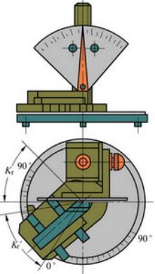 Measure the leading angle Deflection angle
  Inner measuring blade inclination
  Rotate the measuring stand so that the main cutting edge is attached to the large surface of the large index plate. At this time, the large index plate coincides with the cutting plane of the main cutting edge of the turning tool. According to the definition of the blade inclination angle, the bottom surface of the large index plate is attached to the main cutting edge (Figure 4), and the inclination of the blade can be read on the large scale plate. Value (note
  Positive and negative).
 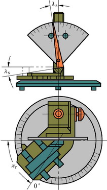 Inner measuring blade inclination
  Internal measurement front angle
  Rear corner
  Rotate the measuring table counterclockwise from the original position (90°- The plane where the large-finger piece is located is the main section of the main cutting edge of the turning tool. According to the definition of the front corner, adjust the large nut so that the bottom surface of the large index finger fits the rake face (Figure 5).
 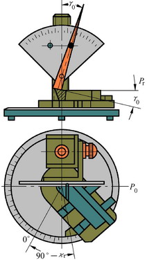 Internal measurement front angle The value of When the back angle is measured, the gauge table is at the same position as above. According to the definition of the back angle, the large nut is adjusted so that the side of the large index piece is attached to the back flank (Fig. 6) and can be read out on the large dial. angle The value of
 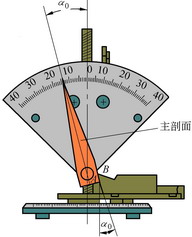 Internal measurement back angle
The commonly used turning tools include a straight outer turning tool, an elbow turning tool, an eccentric cutting tool, and a cutting tool. When measuring the geometry of the turning tool, it is necessary to prepare a universal turning tool angle table and a turning tool to be measured on the workbench.