In the current electronic systems, the negative power supply is disappearing, the positive power supply voltage is also gradually decreased. This trend makes the track-to-rail amplifier is increasingly popular. Although the supply voltage is constantly changing, the signal level usually remains constant. For example, the standard video signal is 2V, and when the supply voltage is reduced to 2V, the amplifier / buffer must operate linearly and accurately over the entire 2V range. This article will focus on the development of the rail-to-rail amplifier input stage, and discusses input-enhancement circuits that overcome the shortcomings of rail-to-rail amplifiers. For the sake of simplicity, our discussion is limited to MOSFET amplifiers. Figure 1 shows the basic op amp input stage. A pair of transistors called differential pairs are located at the upper end of the current source to accommodate differential inputs. Although this topology can provide differential gain and suppress common-mode signals, its limitations lie in its operating range. Under single-supply condition of 3V, the input voltage range is 0 ~ 1.5V. If the input voltage is higher than 1.5V, the current source will be forced out of saturation. Once the current source leaves the saturation region, the gain will be distorted. For example applications such as current sensing or voltage sensing, such as EKG, the quality of the design is directly related to the range of signal voltages that can be handled. This challenge is addressed by the standard rail-to-rail op amp topology, which has two input stages (as shown in Figure 2). The PMOS transistor pair amplifies the signal when the input voltage approaches the low voltage rail. In contrast, the NMOS differential pair amplifies the input signal close to the upper voltage rail. In this way, the input voltage range can be the entire supply voltage range. The most obvious tradeoff for this improvement in input voltage range is the need for an extra power supply to bias the complementary differential pair. There is a less significant trade-off of the bias voltage relative to the input bias voltage. The bias of the NMOS pair does not have to match the bias of the PMOS pair - the polarity is reversed when biased. Near the middle of the supply voltage, there is a switch from one pair to the other. During switching, the bias voltage is the average of the bias voltage for each pair. This creates a ladder of characteristics (Figure 3). For a better understanding, the figure gives the bias voltage for different temperatures. PMOS input pairs activated at a low common-mode input voltage exhibit a wide range of bias voltages relative to temperature. The change in the NMOS pair results in the distribution of the right common-mode input voltage on the right-hand side of the figure. Figure 3: Input Bias Voltage vs. Input Common-Mode Voltage. As mentioned earlier EKG detection applications, any changes in bias voltage will affect the accuracy of the system. The signal must first be amplified much higher than the bias voltage to take advantage of the rail-to-rail amplifier topology shown in Figure 2. In high-precision and low-power applications, a new type of rail-to-rail amplifier is needed. The goal is to get the full range of input voltages without cross-bias voltage distortion that occurs during the switching in a double-difference design. Let's go back to the single difference design. The input range of the topology shown in Figure 1 does not support the entire range of input operations. Part of the input range is reserved for bias current in the saturation region. Can the current source be biased in a way that allows input across the rails? Input op amps are included in op amps like the EL8178 to adjust the internal bias supplied to the current source. Figure 4 shows this innovative topology. In the enhancement circuit is a charge pump. Although charge pumps often cause noise problems, the operating frequency of the charge pump far exceeds the amplifier's bandwidth. Therefore, the amplifier noise performance will not be significantly changed. Figure 4: Rail-to-Rail Input Stage with Input Range Enhancement Circuit In addition, we must reconsider the problem of bias voltage. Figure 5 achieves the goal of maintaining the bias voltage. Input range enhancement circuitry allows a single op amp pair to provide rail-to-rail operation without the need for additional complementary differential pairs. The bias voltage is completely determined by the mismatch of only one set of transistors, so there is no crossover area. Careful layout and trimming ensures that the input reference bias voltage is less than 100V. Figure 5: Enhanced Input Rail-to-Rail Input Bias Voltage vs. Input Common-Mode Voltage. So far, our discussion has been limited to MOSFET implementations. Bipolar technology can also benefit from this configuration. In addition to improving the bias voltage, bipolar technology can achieve similar improvements in input bias current. The input bias current is only provided to one matched differential pair, not two differential pairs with crossed regions. These are the evolution of rail-to-rail amplifiers. The basic input stage consisting of a differential pair does not allow the input of a full range of voltages. The double differential pair extends the input voltage range to the supply voltage, but the bias voltage (and the bias current in the BJT) is non-linear due to the switching between the two pairs. The third solution includes an internal enhancement circuit to adjust the current source bias of a single differential pair to achieve rail-to-rail operation at bias voltage continuous conditions. Table 1 summarizes the performance of the three example op amps. The final version of the EL8178 provides the specifications required for low-power, high-resolution systems such as portable EKG machines. Table 1: Op Amp Performance Characteristics with Three Different Input Levels. Search Keyword: More Valve Technology Information
Rubber
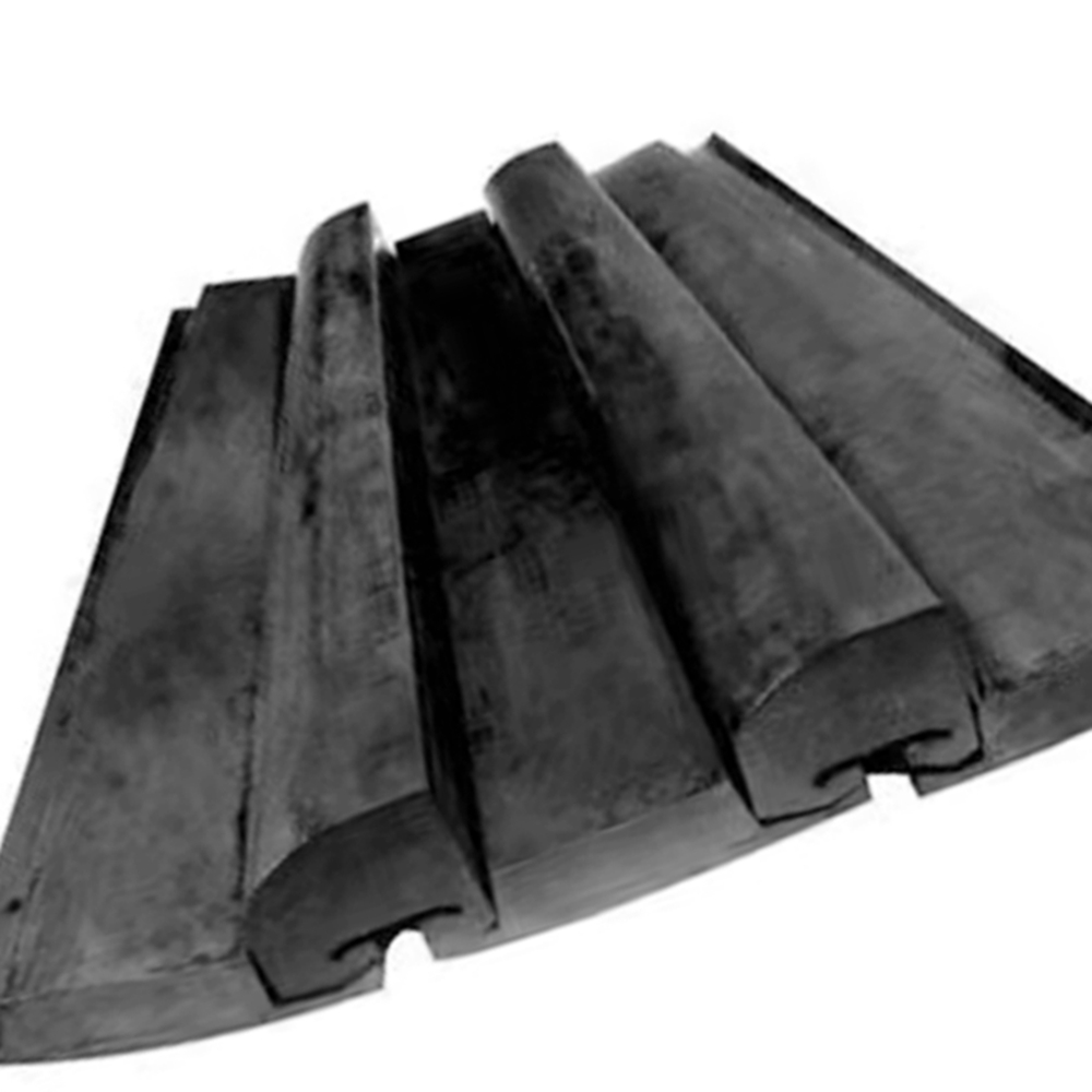
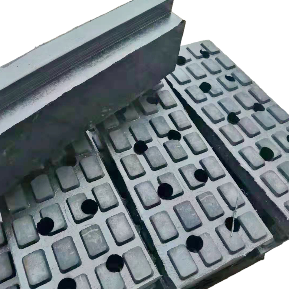
Liner is mainly used in AG Mill, SAG Mill, Ball mill, Bar mill and other
grinding equipment for mining, cement, chemical industry, building
materials, metallurgy and other fields.
The advantages of Wear Resistance Rubber Lining of ball mill
1.
shock resistance, corrosion resistance, wear resistance, acid and alkali
resistant,
2.
light weight
3.
lower noise
4.
few energy consumption
5.
longer service life
6.
east installation and so on.
The
main products are rubber and plastic seals, polyurethane accessories,
high-pressure rubber hose, conveyor belt, conveyor design and so on. With
excellent quality and service, Abrasion Resistant Rubber Liners are widely welcomed by customers in
many countries.
Due
to the good elasticity of rubber, it can be deformed under the impact of steel
ball, so that the force is small, for soft materials, the life of rubber lining
plate is 2~3 times higher than manganese steel lining plate, and the higher the
hardness of the material, the advantage of rubber lining plate is more
significant corrosion resistance;
Steel
lining plate can be corroded by acidic slurry, but rubber lining plate is not
sensitive to acidic or alkaline media such as water vapor at a certain
temperature, only oil and ozone (generated by high-power motor) corrosion on it
easy to assemble and disassemble;
Rubber
lining for 1/5 ~ 1/6 of manganese steel lining plate of the weight of the same
specification, and tear open outfit is convenient, the installation time just
install manganese steel lining plate of rubber lining board of 1/3 ~1/4 rubber
lining thinner, increase the effective volume of the cylinder liner thickness
usually only 50 mm rubber discharging grating blocking phenomenon of relatively
less steel grating rubber lining work small noise when the defect is: not high
temperature resistant, not suitable for use in dry grinding machine.
Rubber Liner,Cement Ball Mill Liner Plate,Abrasion Resistant Rubber Liners,Ball Mill Spare Parts,Abrasion Resistant Rubber Liner HuiFeng Wear Resistant Group , https://www.hpwearsolution.com
