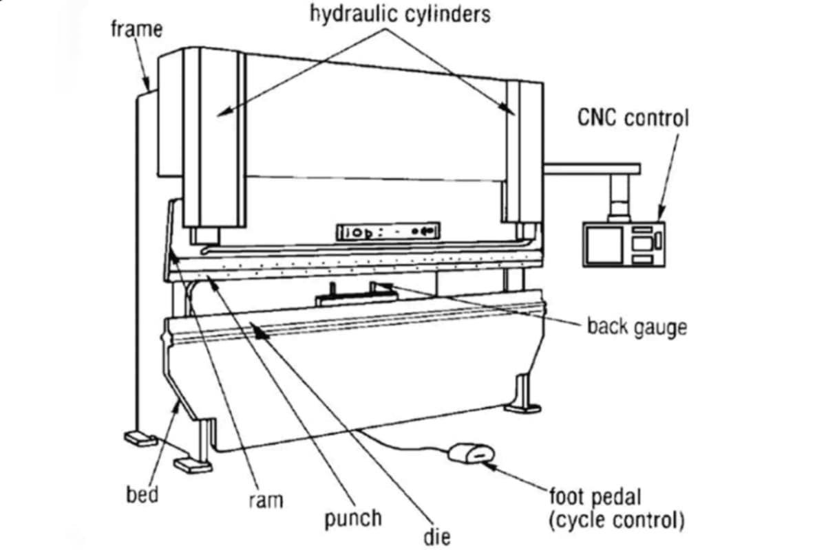
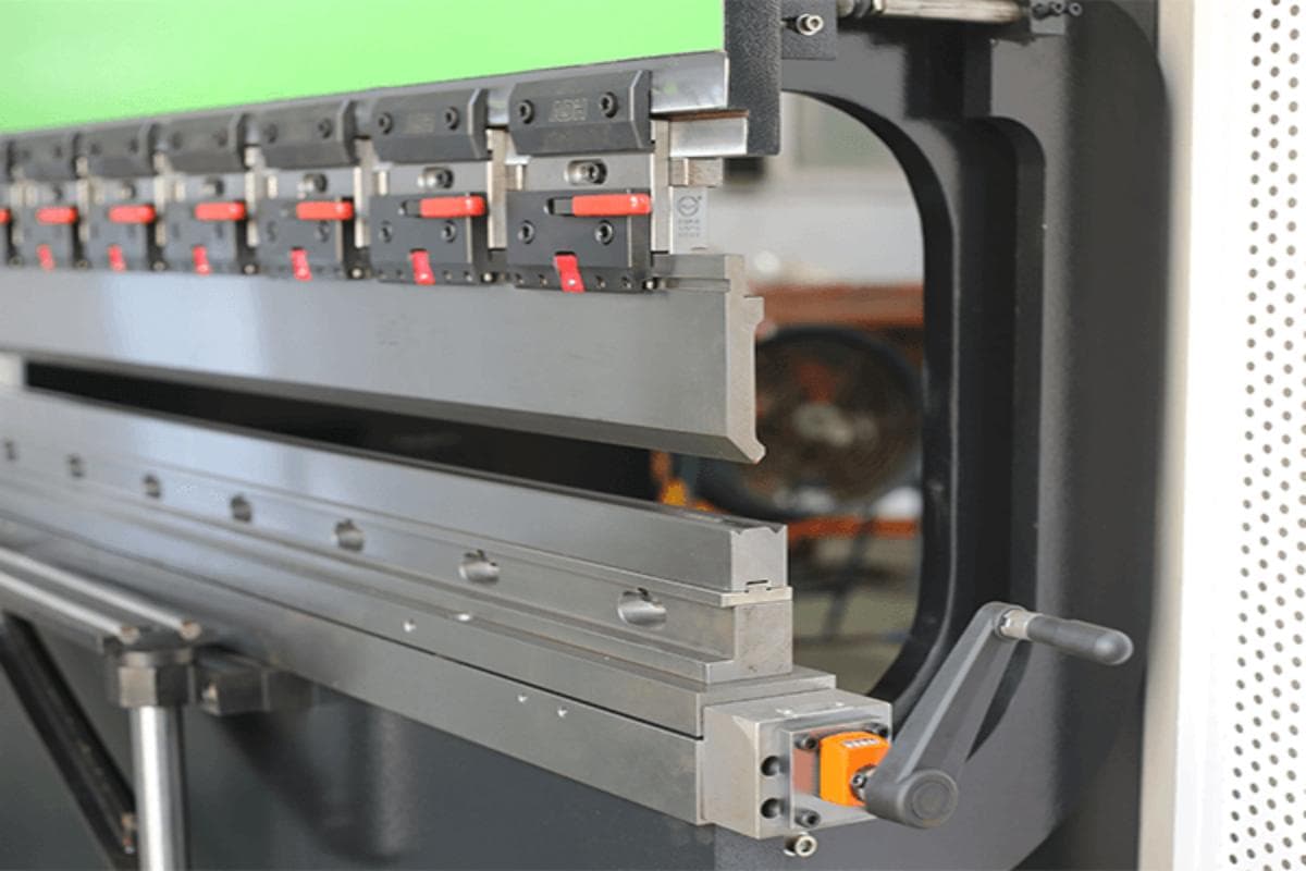
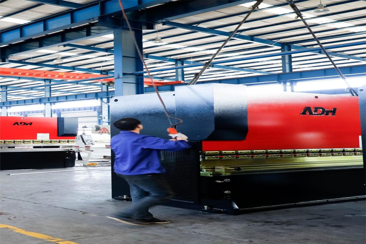
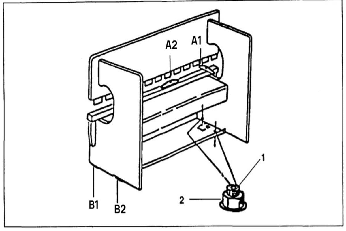
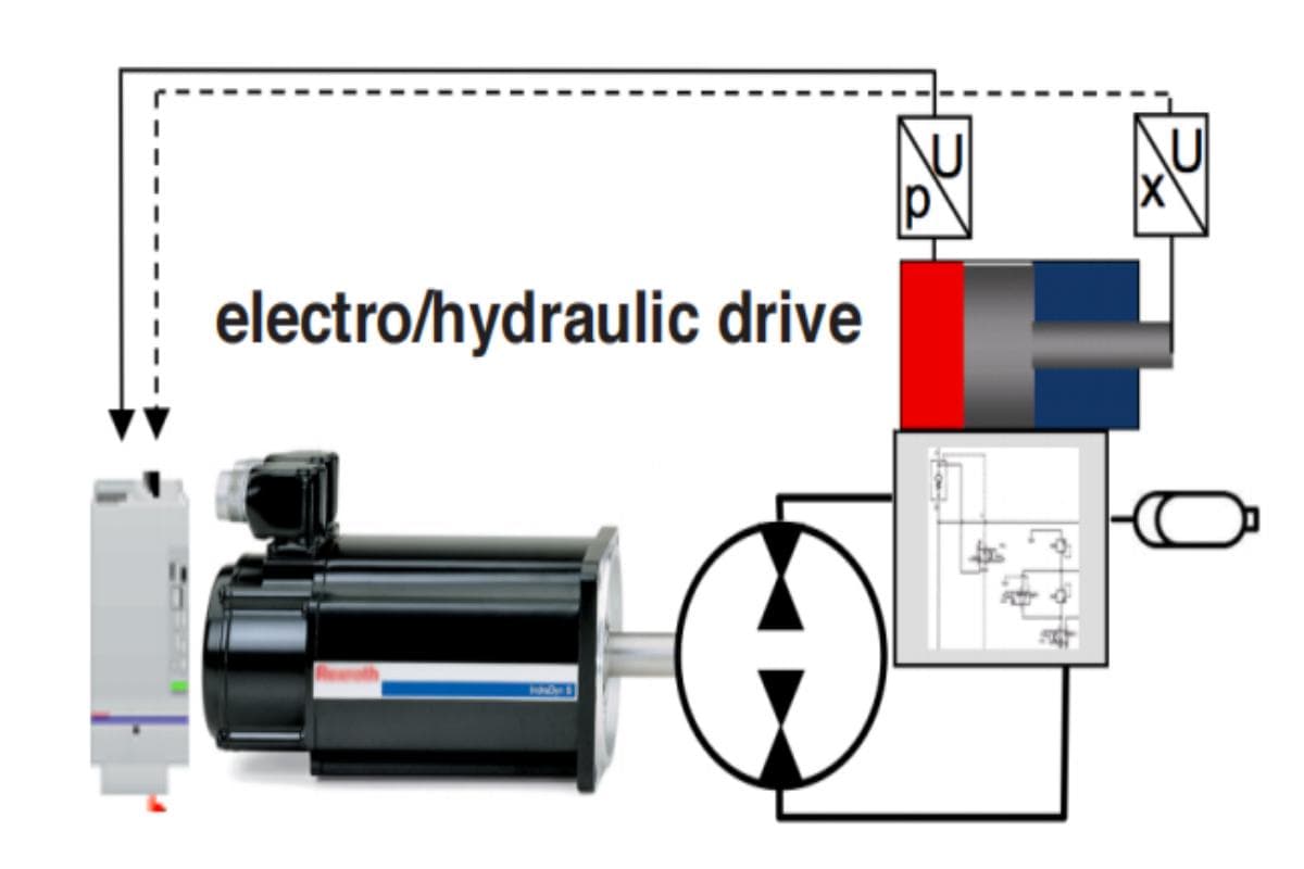
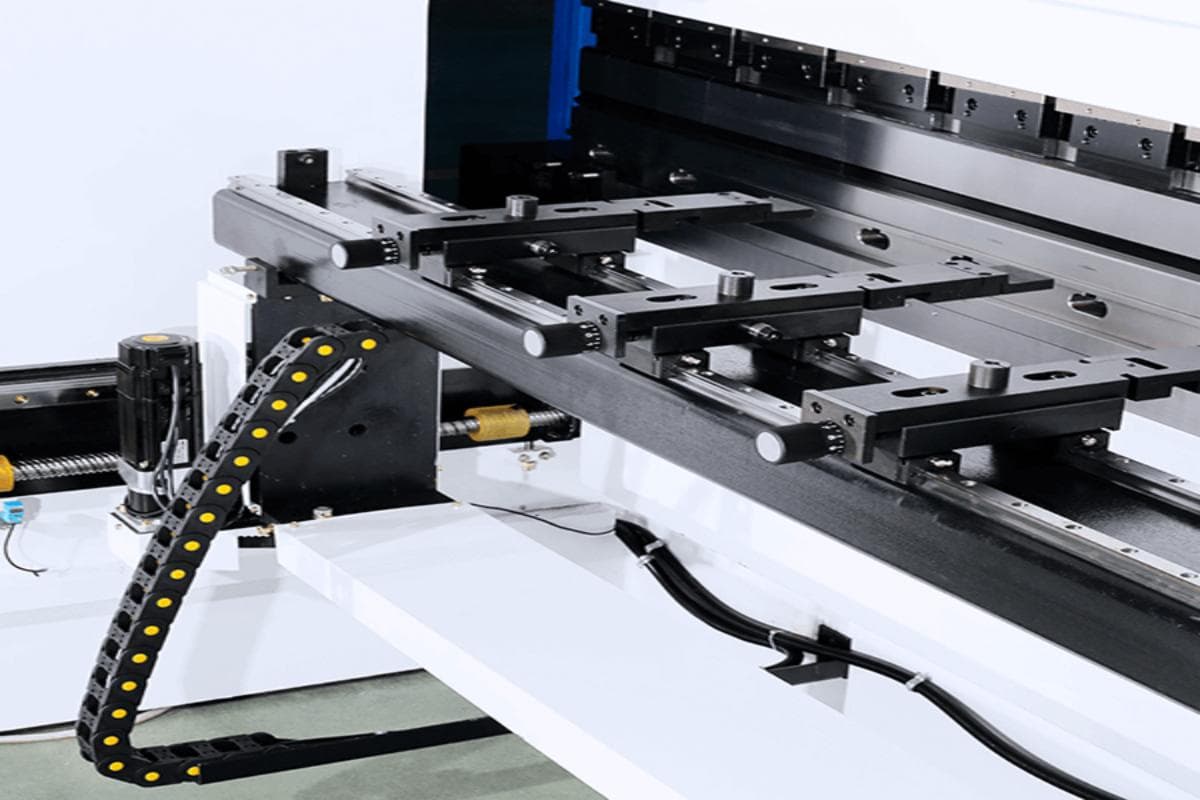
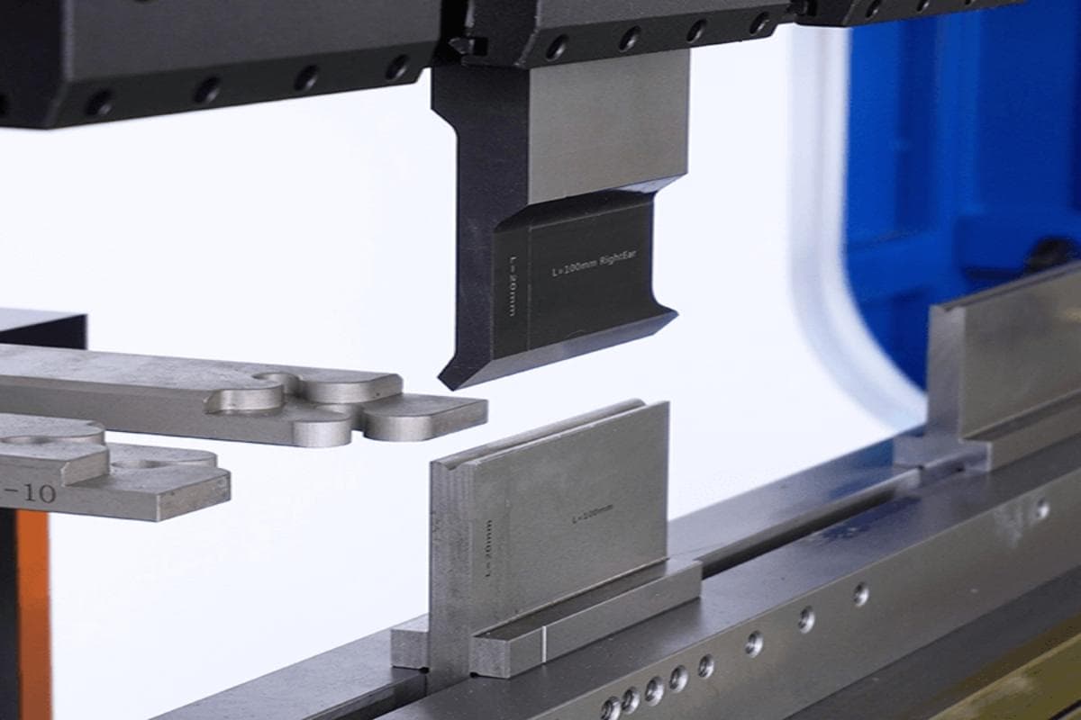
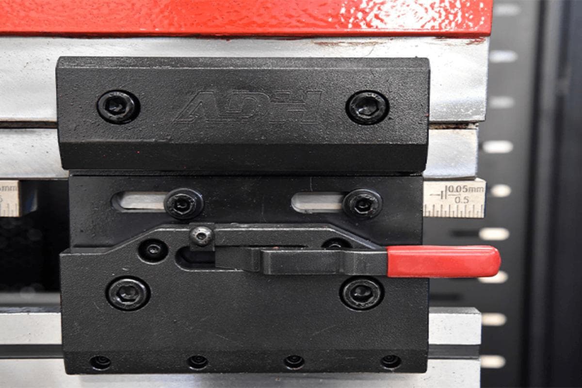
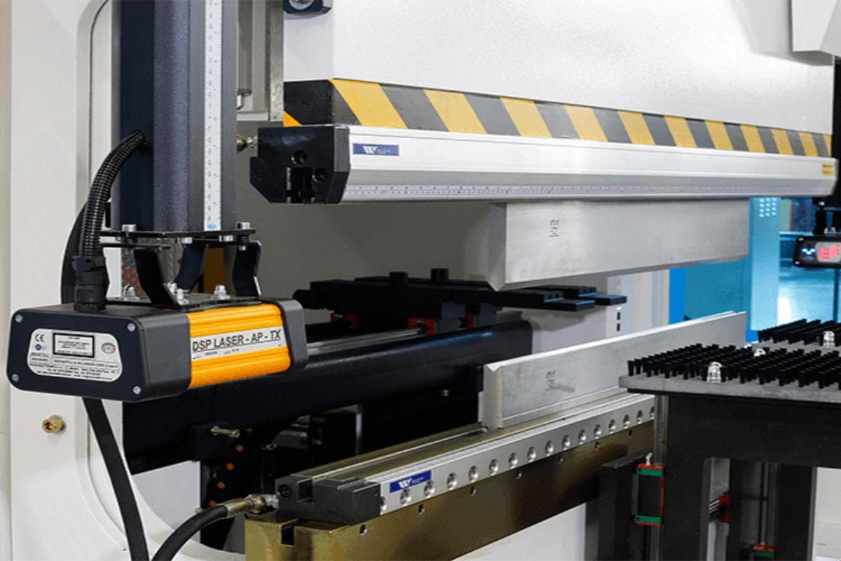
This blog is a comprehensive guide of press brake  (sheet metal bending machine) manual that introduces the operation procedures of a press brake. The following is a brief introduction to the machine. The basic principle of brake forming relies on force, otherwise known as tonnage. Along with the tonnage comes bending length, which is the maximum length of sheet metal that can be bent. The press brake is one such tool that is capable of bending even the largest sheet metal, making it an indispensable and critical piece of equipment in the sheet metal forming and shaping process. The press brake tooling is known as upper punch and bottom of the die. It bends the sheet metal through the upper and lower dies at the ram. Different die and punch can produce profiles with different angles and shapes. There are oil cylinders on the left and right uprights that respectively drive the movement of the ram. The ram moves downward during operation, exerting pressure on the metal sheet against the die. The stroke of the ram is controlled by the hydraulic and electrical systems. The body of the press brake is composed of two vertical steel plate structures. The oil cylinders and hydraulic and electrical control systems ensure the accuracy of repeated bending. There is also a workbench at the bottom of the press brake. To prevent the workbench and ram from deformation due to long-term overload, the hydraulic press brake is equipped with a crowning device that can compensate for the deflection of the workbench and ram. The bending process starts with the metal sheet freely placed on the bottom die. As the top die applies pressure, the bending force arm and radius of curvature decrease, causing the plate to conform to the V-groove of the lower die. At the end of the stroke, the upper and lower form a V-shaped die, completing the bend. You’ll need to know that the common type of press brake is mechanical press brakes, manual press brakes, hydraulic press brakes, CNC press brakes. CNC press brake utilizes modern computer technology to improve accuracy and efficiency, and is equipped with a CNC controller to proceed with complex bending operations. Hydraulic press brakes stand out in the metal fabrication industry for their versatility and precision. Hydraulic system offers controllable and consistent bending force, which reduces manual labor. The material and opening of the die should be selected according to the workpiece and press brake bending method. Bending techniques such as air bending, coining, and bottom bending each have their place in machine operation. In air bending, choosing a narrower die angle allows you to increase the depth of penetration to account for springback, which is the tendency of the sheet metal to spring open slightly after the punch releases bending pressure. Harder materials exhibit more springback, while softer materials conform more easily to the die’s angle. Techniques like coining can offer precise bending, compensating for springback without resorting to bottom bending. In the ever-changing manufacturing industry, using a press brake to bend sheet metal is a common metal forming method used to create finished products from metal materials. The press brake machine is designed for bending sheet and plate material, which is widely used in various industries, including household industries, construction, machinery, automobile, aviation, and others. In order to ensure the bending accuracy of the press brake, the press brake bending needs to be leveled regularly. Place the press brake on the horizontal ground and place the spirit level on A1 and A2 to test its levelness, respectively. A deviation of 1-2 mm per meter is allowed. If the difference is too large, the leveling bolts at the bottom of the press brake need to be adjusted. It's recommended to have professionals check the electrical wiring of the press brake and connect the power supply. The electrical connection of the three-phase system should be in the correct position. When connecting the press brake to the three-phase power supply, ensure the direction of the pump rotation drive motor is correct. If the motor turns incorrectly, the phase of the inlet circuit needs to be changed, but the internal circuit cannot be changed. Afterward, restart the oil pump motor and check the steering. Before checking the rotation direction of the motor, ensure that the press brake has been cleaned and leveled. In the hydraulic drive system of a press brake, the AC servo motor moves the ram and aligns the hydraulic oil with the variable speed pump. The driving device is installed on the beam and connected to the machine body via the guide rail. The press brake control system controls the position of the beam and moves it up and down through the drive motor. Grating rulers on both sides of the press brake read the signal and provide feedback to the control system. The control circuit, filling valve, and servo valve in the oil cylinder are independent and controlled by the DNC controller. A hydraulic or electro-hydraulic servo system can improve bending accuracy and reduce energy consumption and cost. To maintain the cleanliness of the hydraulic system, keeping the oil tank and hydraulic oil clean is crucial. When changing hydraulic oil, wipe the inside of the oil tank with a soft towel, clean the oil tank with clean gasoline, open the valve storing the dirty oil, drain it, and wipe off stains on the oil tank's surface. The hydraulic oil of the press brake should not be used at too low or too high a temperature. If the temperature is below zero or above 70 degrees, an oil heater or cooler can be installed. Fill hydraulic oil through the air filter and operate a press brake to discharge the bubbles in the hydraulic circuit after filling. The back gauge of a press brake is used for positioning the workpiece. To position the workpiece, place it on the lower die and push it into the machine, and the stopper finger of the back gauge will dock with the workpiece. The back gauge's axes can move in different directions via the control system. The X-axis can move forward and backward, the R-axis can move up and down, and the Z-axis can move left and right. Each axis of the back gauge is driven by an independent motor. The Z-axis and R-axis can also be adjusted manually but only from the back of the machine. The linear guide rail and ball screw enable the axes of the back gauge to move freely. The back gauge moves in the X-axis direction, and the force is limited to 150N to prevent collisions. Visual Inspection: Check whether the switch, control, motor, and grounding are in normal working condition. Verify the oil level in the oil tank and the hydraulic system's condition. Idle the machine and maximize the press brake stroke. Check whether the machine is operating normally, the motor's rotation is normal, and the sound is normal. Tooling assembly and alignment: Before installing the punch and die, stop the machine, and install the lower and upper dies. The upper and lower dies of the press brake must be aligned to obtain higher bending accuracy. To align the upper and lower dies, drive the ram downward, bringing the upper dies close to the lower dies, leaving a distance equal to the workpiece thickness. Manually adjust the upper and lower die positions using the lower die bolts and upper die clamps. After aligning the upper and lower dies, drive the ram upward. When turning off the press brake, switch to manual mode, and lower the ram by stepping on the pedal to align the upper die with the lower die. Press the stop button and turn off the main motor. The switch parameter should be set to 0. In case of emergencies, press the emergency stop button, but this will not affect the subsequent procedure since only the axes and pump are turned off. Release the button to restart. Daily Maintenance: The press brake should be regularly maintained and serviced by professionals. This includes lubricating and cleaning machine parts, using high-quality lubricating oil, and weekly lubrication of worn parts. Regular Inspections: The hydraulic system should be regularly checked for oil level and cleanliness, and the hydraulic oil should be replaced as needed. Check the wiring of the electrical cabinet to ensure it is in good condition, and inspect the signal of sensors such as the grating ruler. Additionally, check the tightness of bolts to ensure they are secure. Before using a new press brake, various parts of the machine must be installed and debugged. When replacing toolings and calibrating the backgauge, make sure to avoid injury. ADH is a professional sheet metal machine manufacturer with 20 years of experience. Our product line includes press brakes, laser-cutting machines, and plate shearing machines. We can assist you in choosing the right press brake and provide strong after-sales support. If you need information about our press brake, please contact our sales staff or browse our products. Screw Locking Boring Head Screw Locking Boring Head,Cba Screw Locking Milling,Rba Screw Locking Boring Head,Cba Screw Locking Boring Head SICHUAN JOJO TOOLS CO., LTD , https://www.jojo-tools.comI. Introduction
1. Structure and Working Principle
2. Type of Press Brake
II. Installation of Press Brake
1. Choosing the Right Location
2. Using a Crane
3. Installing the Machine
(1) Machine Leveling
(2) The Connections of Electric
(3) Hydraulic System
(4) Back Gauge of Press Brake
III. Press Brake Operation Basics
1. Pre-Operation Checks
(1) Inspecting the Equipment
(2) Safety Equipment
2. Operation Steps
(1) Setting Up the Machine
(2) Programming (for CNC Press Brakes)
(3) Bending Operation
3. Shut down the machine
IV. Press Brake Maintenance
V. Conclusion