Shenzhen Stardeal Industrial Co.,Ltd , https://www.plasticblisterpacks.com
Description of the Invention The utility model relates to the technical field of water meters, in particular to a smart water meter with a water quality detection function.
BACKGROUND OF THE INVENTION A smart water meter is a new type of water meter that uses modern microelectronics technology, modern sensor technology, and smart IC card technology to measure water consumption and transmit water data and settlement transactions. Compared with the traditional water meter, which only has the functions of flow collection and mechanical pointer display of water consumption, it is a great progress. In addition to recording and electronically displaying water consumption, smart water meters can also control water consumption according to the agreement, and automatically calculate the water fee for the stepped water price, and can also perform the function of water data storage.
However, when the existing smart water meter is used, since there is no regular monitoring function, the water flow in the water meter is continuously monitored in real time, which consumes a large amount of electric energy. For the smart water meter with built-in power supply, it needs to be replaced frequently. The battery, to bring the same to the user, for this, we proposed a smart water meter.
SUMMARY OF THE INVENTION The purpose of the present invention is to provide a smart water meter with a water quality detection function, so as to solve the problem of high energy consumption of the traditional water meter proposed in the above background art. 
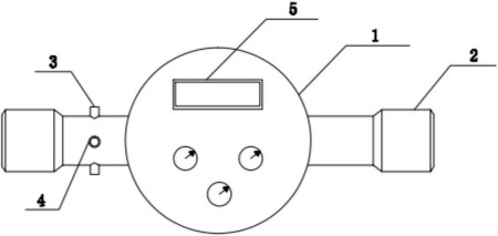
The figure is a schematic diagram of the utility model
Preferably, the left and right ends of the connection water pipe are provided with a demountable bayonet, and the end of the demountable bayonet is covered with a sealing ring. The inserting groove is located on the perpendicular line between the two sets of mounting grooves, and the position of the inserting groove is U-shaped open groove. The data exchange unit is internally provided with an external communication interface. The storage module is internally provided with multi-level storage units, and a conversion interface is provided between the two groups of storage units.
Compared with the prior art, the utility model has the beneficial effects that the sensor adopts the timing control and the power consumption is very low, and can fully meet the use requirement of the water meter powered by the built-in power supply, and the position of the slot module is installed at the front end of the water meter. After improvement, it can realize multiple usages of multiple modules using one module and one table to install one module. It can monitor the turbidity and flow of water quality in the water pipe, and can alarm through the buzzer alarm when the water quality, flow rate and valve are abnormal. Remind users of attention.
For more information, please download the full specification of the patent.
More information on the latest technology of meter technology patents, please continue to pay attention to [instrument patents]
[Chinese instrument network meter patent] creative limit, instrumentation invention. Today we introduce a national patent for invention—a smart water meter with water quality detection function. The patent was applied for by Chengdu Sanyu Instrument Technology Development Co., Ltd. and was authorized to be announced on February 8, 2017. In order to achieve the above objectives, the utility model provides the following technical solutions: an intelligent water meter with a water quality detection function, including a water meter housing, a water pipe is symmetrically installed on the left and right sides of the water meter housing, and the top and the bottom of the connecting water pipe on the left are symmetrical. An installation slot is provided, an outer wall of the connecting water pipe on the left side is provided with an embedded slot, an LCD display screen is arranged on the surface of the water meter housing, the LCD display screen is electrically connected to the micro processor, and the micro processor is respectively powered The bidirectionally connected data exchange unit, the clock unit and the storage module are electrically connected to the user input query unit, and the micro processor is respectively electrically connected to the valve control unit and the alarm prompt circuit, and the alarm prompt circuit is electrically connected. The voice output is connected to a buzzer alarm. The micro processor is electrically connected to a power circuit, a turbidity sensor and a measuring sensor, respectively. The turbidity sensor and the measuring sensor are electrically connected to the timing module.