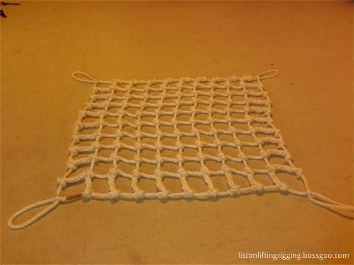
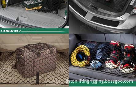
A cargo net is a type of net. It is usually square or rectangle, but sometimes round, made of thick rope, with cinch ropes extending from the corners, and in some designs, the edges. It is named for its use in transferring cargo to and from ships. We provide auto cargo net ,cargo net for climbing tasks and nets for cargo protections.
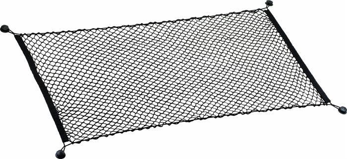
These stretch cord nets are a great alternative to trying to use multiple bungee cords, quickly surrounding and keeping a tight hold on your cargo. Each net has multiple hooks to secure it to a basket rail, roof rack bar, or another tie down point.
Technological Process
--Raw material
--Plyinig and warping
--Braided Netting
--Cutting different dimensions
--Sewing into finished Trailer Cargo Net
--Packaging with insert (label) into carton
--Inspection(raw material, process, pre-shipment)
--Entering warehouse
--Loading container
Products show
Our advantage:
1.small quantity we accept.
2. Well and high quality control
3. Competitive price
4. OEM welcome
5. Considerate service
6. Delivery in time
We can provide:
Cargo Net,Cargo Netting,Truck Cargo Net,Climbing Cargo Net Hebei Liston Lifting Rigging Manufacturing Co., Ltd. , https://www.liftingriggingfactory.com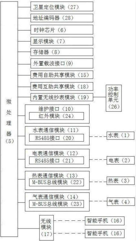
Figure is a schematic block diagram of the circuit connection structure of the utility model of a water meter and a hot meter gas meter four-in-one converter 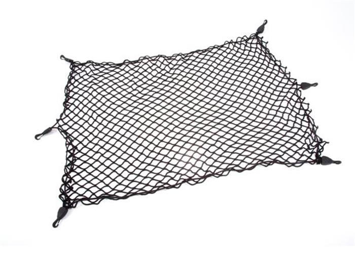
Quality guarantees with test reports on request
Short sample and production lead times
Professional services
Our products feature colorfastness and anti-UV and AZO free functions.
OEM and ODM designs are welcomed.
We sincerely hope that we can cooperate with you in the near future!
[Chinese instrument network meter patent] creative limit, instrumentation invention. Today, we introduced a national patent for invention—a water meter, a hot-air meter, and a four-in-one converter. The patent was applied for by State Grid Zhejiang Electric Power Co., Ltd., Huzhou Power Supply Company, State Grid Corporation of China, State Grid Zhejiang Changxing County Power Supply Company, and Hangzhou Xili Intelligent Technology Co., Ltd., and was authorized to announce on June 13, 2017.
Content Description
The utility model relates to the technical field of converters, in particular to a four-in-one converter of a water meter, a hot meter and a gas meter.
Background of the invention
At present, water meters, electricity meters, heat meters, and gas meters use separate acquisition devices to implement wireless meter reading. However, data collection for water meters, electricity meters, hot meters, and gas meters are installed separately at the user's office. The acquisition equipment collects data. Therefore, to collect the data of these four types of tables, it is necessary to install the corresponding four collection equipments at the user, which not only results in a high installation cost of the collection equipment. In addition, after the user purchases the four types of energy consumption, namely the required energy consumption for water, the required energy consumption, the required thermal energy consumption and the required energy consumption, the four energy consumptions purchased by the user. Between the various energy purchase fees, free interconversion is not possible, so that the users cannot freely convert each energy consumption amount after purchasing the four energy consumption amounts.
Summary of the Invention
In order to solve the shortcomings and deficiencies existing in the prior art, the utility model provides a four-in-one converter of a water meter, a hot meter and a gas meter capable of performing free energy metering after the four energy consumption amounts.
In order to achieve the above technical goals, the utility model provides a water meter, a hot gas meter, and a four-in-one converter, which can convert the data of the water meter (1), the meter (2), the heat meter (3) and the gas meter (4) separately. The device body is characterized in that the converter body comprises a microprocessor (5), a clock chip (6) respectively connected to the microprocessor, a display module (7), a memory (8), an external carrier interface (9), Maintenance interface (10), water meter communication module (11) connectable to the water meter, meter communication module (12) connectable to the meter, heat meter communication module (13) capable of connecting with the heat meter, and connection with the gas meter The gas meter communication module (14); the converter body further comprises a fee self-service sharing module (15) respectively connected with the microprocessor and a wireless module (17) wirelessly connectable with the user's smart phone (16).
Optionally, the converter body further includes a cost mutual-aid sharing module (18) connected with the microprocessor. It also includes a built-in wireless meter reading module (19) connected to the microprocessor. The water meter communication module and the meter communication module respectively include an RS485 interface. The hot meter communication module and the gas meter communication module respectively include one M-BUS bus module. The maintenance interface includes an infrared module (24). The converter body also includes a satellite positioning module (27) and an address encoder (28) which are respectively connected to the microprocessor.
The converter body further includes a power control unit (26). The power control unit includes a signal sampling module (100) and a subsequent output module. The following output module includes: a resistor R6, a resistor R7, a resistor R8, and a capacitor C7. Capacitor C8, signal ground SGND, transistor Q1, transistor Q2, connection point No. 5 (55), connection point No. 6 (66), connection point No. 7 (77), connection point No. 8 (88) and supply pin; resistance R6 One end is connected to the output end of the signal sampling module, and the other end of the resistor R6 is connected to the seventh connection point; one end of the resistor R8 is connected to the seventh connection point, and the other end of the resistor R8 is connected to the eighth connection point; One end of the capacitor C8 is connected to the seventh connection point, the other end of the capacitor C8 is connected to the eighth connection point, the base of the transistor Q2 is connected to the seventh connection point, and the emitter of the transistor Q2 is connected to the eighth connection point. The collector of the transistor Q2 is connected to the connection point No. 6; the signal ground SGND is connected to the connection point No. 8; the base of the transistor Q1 is connected to the connection point No. 6; the emitter of the transistor Q1 is connected to the connection point No. 5 , the collector of transistor Q1 At the seventh connection point, one end of the resistor R7 is connected to the fifth connection point, and the other end of the resistor R7 is connected to the sixth connection point. One end of the capacitor C7 is connected to the fifth connection point, and the other end of the capacitor C7 is connected. At the sixth connection point, the power supply pin is connected to the fifth connection point; the sampling end of the signal sampling module is connected to the built-in wireless meter reading module.
Optionally, the converter body further includes a power supply module (25) capable of providing required power for each of the electrical devices in the converter body; the power input terminals of the respective power consumer devices in the converter body. The corresponding power output connection of the power module is provided. The power module includes a standby power source (29) and a main power source (30) directly connectable to the mains (47); the standby power source includes a first node (32), a second node (38), and a third node (34), lithium sulfuryl chloride battery (31), capacitive lithium ion battery (40), diode (37), fuse (33), sliding rheostat (35), positive battery interface (36), and negative battery interface (39) The positive terminal of the lithium thionyl chloride battery, the positive terminal of the capacitive lithium ion battery and the one end of the fuse are all electrically connected to the No. 1 node, the other end of the fuse, the one end of the sliding varistor, and the slide of the sliding varistor ( 45) Electrically connected to No. 3 node, and the other end of the sliding varistor is electrically connected to the positive electrode interface of the battery, and the negative terminal of the lithium sulfuryl chloride battery is electrically connected to the negative terminal of the diode. The negative terminal of the capacitive lithium-ion battery and the battery negative terminal are all electrically connected to the second node.
The standby power source further includes a sliding cavity tube (44) sealed at the right end and having a sliding hole at the left end. A sliding block (42) is slidably disposed in the sliding cavity tube so as to form a sealed cavity in the sliding cavity tube at the right of the sliding block. The sealing cavity is provided with a thermal expansion and contraction solution (43), an insulating sliding bar (41) is slid in the sliding hole, and the left end of the insulating sliding bar is fixedly connected to the sliding plate of the sliding varistor; the thermal expansion and contraction solution is Mercury (46).
The technical solution provided by the utility model has the following beneficial effects: through the unified meter reading of the water meter, the electricity meter, the hot meter and the gas meter, and the user once purchased the necessary water consumption energy amount, the required electricity consumption amount, and the need After the four energy consumption amounts of the thermal energy consumption and the required energy consumption of the gas, the energy purchase fees of the four energy consumption amounts purchased by the user can also be freely converted between the energy purchase fees, and the user is purchasing the energy. After these four energy consumption quantities, each energy consumption can also be converted freely.
For more information, please download the full specification of the patent.
More information on the latest technology of meter technology patents, please continue to pay attention to [instrument patents]