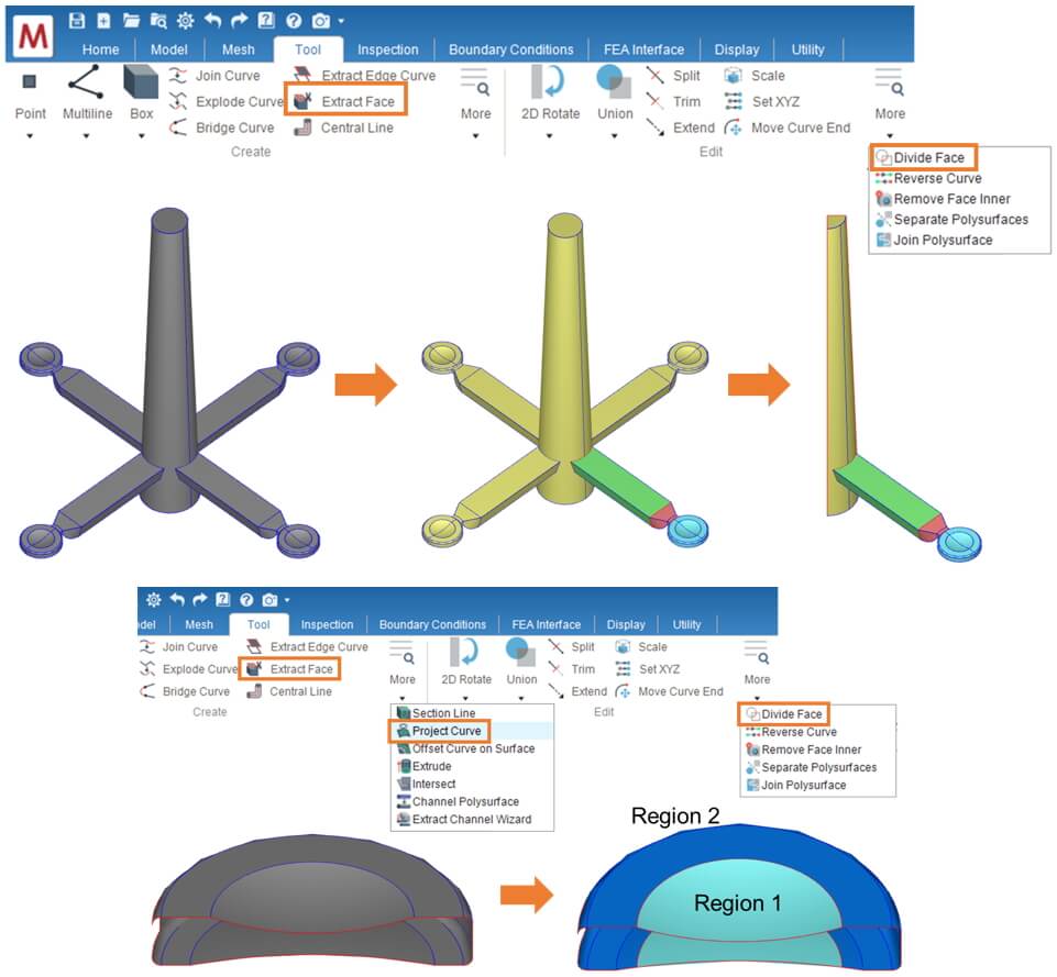
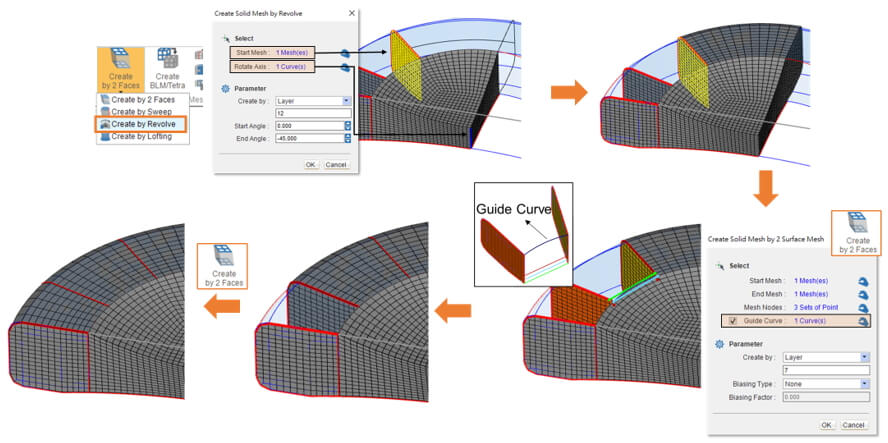
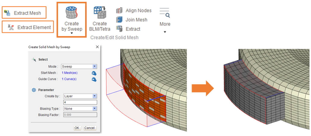
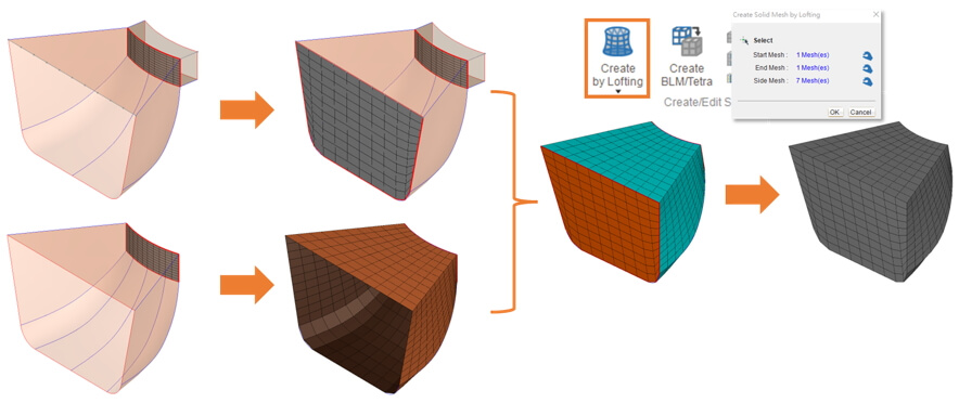
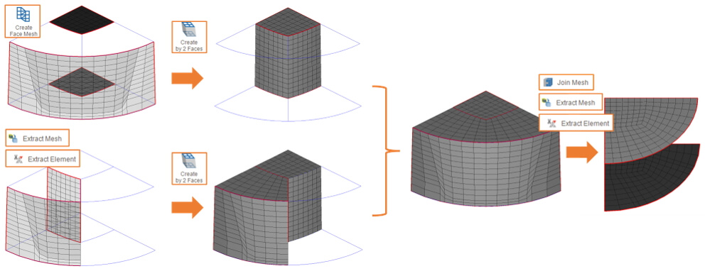
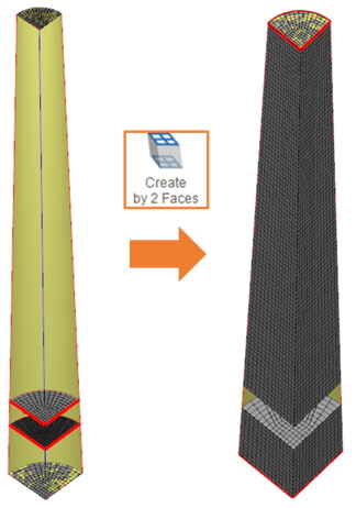
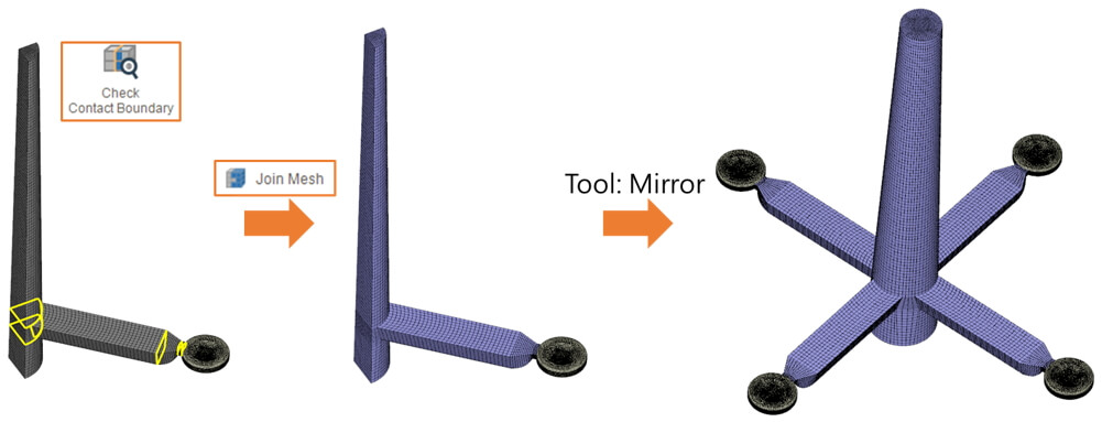
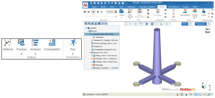
Mesh is one of important part in molding analysis. After the complex geometry model divided into fine elements, the analysis results then can be obtained through solver. Thus, a better mesh quality can help for more accurate analysis results. For thick or simple product, a great mesh model can be generated by the auto-meshing function. However, for small or mesh-quality-sensitive product, such as optics, RTM, or special process, it is recommended to create mesh manually which is easier to control the mesh quality. Structure Mesh in Moldex3D Studio provides a variety of tools for surface mesh and solid mesh generation during pre-processing. For products requiring fine mesh, Structure Mesh enables creating mesh manually with more flexibility for different user scenario. The following will demonstrate how to manually create mesh in Studio for a multiple cavity molding case of four lenses. Step 1. Prepare model: divided geometry Import the geometry model in Studio project. As shown below, use tools such as Project Curve, Extract Face and Divided Face in Tool Ribbon to divide model and get the necessary faces and feature line for building mesh. The model here is simplified to 1/4 symmetry with all attributes set for each component. For an introduction to the functions in the Tool Tab, please refer to other related sections. Step 2. Generate part mesh Click Structure Mesh to enter Structure Mesh Ribbon. Click O-grid Face and select the Center Point, Point of Radius and Point for Region 1. Click OK, and an O-grid face with 12 surfaces is then generated. Use the O-grid face to divide two Region 1 faces with function Extract Face and Divide Face for surface mesh structure. Note: Structure Mesh is only available in Solid mesh mode and requires Mesh license. Â Â For the quarter of Region 1, use Seeding, Create Face Mesh, and Combine to create surface meshes for three faces and merge them into one surface mesh. Repeat for the same quarter on the bottom, and use Create by 2 Faces to generate a solid mesh by selecting two surface meshes. Note: Please make sure that the seeding should be the same on contact edge between different faces. When Create by 2 Faces is used, if the topology or node selection is different, it will fail to generate solid mesh. The functions of Guide Curve and Biasing can be used if needed, but there is no biasing and extra guide line setting in this case. Â Click Planar Surface to generate a surface on the side face of Region 2. Use Seeding, Create Face Mesh, and Combine again to create surface mesh on the side, and then use 3D Rotate to copy the surface mesh to the joint of feature lines, as shown below. Â After surface mesh prepared, use Create by Revolve and Create by 2 Faces to generate the solid meshes of Region 2. Â After solid meshes of Region 1 and Region 2 are completed, click Check Contact Boundary to check whether the meshes are matched on contact face. As shown below, there are non-matching faces between Region 1 and 2, so click Align Nodes to match the nodes between different meshes. Then, set solid mesh with attribute of Part and click Mirror in Tool Ribbon to generate for a full solid mesh of the lens and combine them into 1 as the figure below. Note: It is necessary to define the solid mesh attribute before joining solid mesh, otherwise, the warning message is popped up to alert user. Step 3. Generate gate mesh Click Extract Mesh and Extract Element to select the elements contacted with melt inlet. Use Create by Sweep (select either between modes) to generate the gate solid mesh along the geometric edge. Â To create solid mesh for the other part of Gate, as the figure shown, use Extract Mesh and Extract Element to get surface mesh from solid mesh just created, use Seeding and Create Face Mesh to create surface mesh on the other faces. Then, click Create by Lofting, select Start Mesh (orange), End Mesh (orange), and Side Mesh (blue). Click OK to create a solid mesh. Step 4. Generate runner mesh Click Extract Mesh and Extract Element to obtain the gate surface mesh as the start mesh of runner. Use Surface from 4 Curves, Seeding, Create Face Mesh, and Combine to generate the end mesh. Then, the runner solid mesh is created by the two surface meshes. Â Then, create the sprue runner solid mesh. As the figure shown, use O-grid Face and Divide Face to isolate a quarter surface. After, create the surfaces and surface meshes on the two sides. Â Create surface meshes at the center surface and generate solid mesh by two surface meshes. As the figure shown, extract the side elements and generate solid mesh by two surface meshes. It is noted that the layers are the same. After a quarter solid mesh is joined, extract the elements of upper surface and lower surface. Â Next, the rest sprue runner and slag are generated. Use a quarter O-grid surface to generate a surface mesh. Click Create by 2 Faces to create the solid meshes of sprue runner and slag as the figure shown. Â Click Check Contact Boundary to inspect the sprue solid meshes. Set attribute for solid mesh and join all the runner meshes after mesh nodes are aligned. Use Mirror to generate solid mesh for the other 3/4 cavity and combine into a full mesh model. Step 5. Analysis Set the Material, Process, Analysis and Computation Parameter in Studio. Then submit the Run to analyze. Nestled in the heart of innovation and manufacturing excellence, our company stands as a beacon for garden tool enthusiasts and professionals alike. We are proud to introduce our flagship range of Convenient Pruning Machinery, meticulously designed to revolutionize your gardening experience. Among our offerings, the Portable Stihl Garden Trimmer stands out as a versatile companion for all your trimming needs, blending power with portability to ensure that every hedge and every shrub is perfectly sculpted. Our expertise extends further with the Lithium Battery Hedge Trimming Plant Machine, a marvel of modern technology that harnesses the efficiency of lithium batteries to deliver unmatched performance. Say goodbye to the hassles of cords and fuel, and embrace the future of pruning with our battery-powered wonder. For the tasks that demand sheer power, our High Power Gasoline Saw Garden Tool is an indispensable ally. Engineered to tackle the thickest branches with ease, it's the embodiment of reliability and strength, making it a must-have for any serious gardener or landscaper. Experience the difference with our cutting-edge garden tools, where precision meets durability, and where every cut is a testament to our commitment to excellence. Convenient Pruning Machinery,Portable Stihl Garden Trimmer,Lithium Battery Hedge Trimming Plant Machine,High Power Gasoline Saw Garden Tool Henan Lukewei Road Machinery Manufacturing Co.,Ltd , https://www.lukeweimachinery.comMillie Lin, Engineer at Technical Support Division of CoreTech System (Moldex3D)

