Economizer And Air Preheater, Air Heater Of Steam Boiler,Air Preheater In Boiler,Air Preheating System Aph Jinan Yuanda Power Equipment Co.,Ltd. , https://www.jnyuandaboilers.com
2. The electronic amplifier circuit consists of a demodulator, an oscillator, an oscillation control amplifier, a current detector, a current control amplifier, a current limit controller, a reference voltage, a voltage regulator, and the like. By detecting the capacitance signal, they control the oscillation frequency and convert it into a current output.
Second, the sensor component of the test sensor is faulty, generally can not be repaired at the scene, only the replacement. If you do not find such phenomena as damage of the diaphragm, oil leakage, etc., then the following steps can be used to detect the sensor components:
1. Carefully pull the sensor unit outlet out of the connector.
2. Check the forward and reverse bias of the internal diode circuit: one loop is the red line and the yellow line, and the other is the green line and the blue line. The principle is shown in Figure 1. 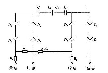
3. Check the resistance of the sensor module housing and the four wires, that is, check the resistance between the capacitor plate and the sensing diaphragm of the housing. The resistance value should be greater than 10 MΩ.
Third, troubleshooting 1151 capacitive transmitter fault location is generally divided into two categories: sensor failure and electronic detection and amplification conversion failure. Sensors are generally not prone to problems. In the case of normal detection according to the above method, there is generally no doubt. Should focus on detecting the circuit part. The 1151 capacitive transmitter's fault phenomenon mainly has the following kinds:
1. The output is too large In the absence of pressure (differential pressure), the transmitter output current (mA) is too large, sometimes over-range, adjust the zero and range potentiometer does not work. There are many parts of the circuit where this fault occurs, and often the damage is the rear pole of the circuit, that is, the current control amplifier to the current control output part. Its structure is shown in Figure 2. 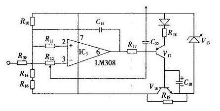
2. Output too small or no output Check whether the voltage applied to both ends of the transformer is normal; whether the voltage across the integrated operational amplifier is normal; determine whether the oscillation circuit starts to vibrate; whether the range, zero, potentiometer adjustment voltage changes and whether the 15Ω range load resistance damage. Detect the back-polarity circuit by detecting the output too large and determine whether the back-polarity circuit is normal.
3. Output instability Check whether the transformer has intermittent short circuit, open circuit and multi-point grounding phenomenon; check the voltage added to the transformer is stable and normal; voltage regulator circuit is normal; detect each zener diode, test the oscillation frequency is stable; Whether or not the circuit board is soldered.
4. Output nonlinearity This kind of fault appears relatively more and it is difficult to detect, and the various parameters of the circuit may cause such failures. But it mainly appears in the nonlinear adjustment circuit part. Its circuit is shown in Figure 3. 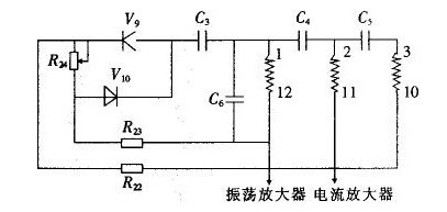
1151 series of capacitive pressure, differential pressure transmitter in the long-term operation, the emergence of a wide range of failures. When dealing with faults, careful detailed observation and analysis should be performed to determine the general location of the fault and the solution steps, and then debugging and testing should be started. This can achieve a multiplier effect. In addition, the user is reminded to note that the meter must be calibrated and qualified after being repaired before it can be put into normal use.
I. 1151 Pressure Transmitter Differential Pressure Transmitter Fault Theory The 1.1151 Series Capacitive Transmitters have a variable capacitance sensing assembly called the “δ†chamber. The sensor is a completely enclosed component. The process pressure and differential pressure are transmitted through the diaphragm and the filling liquid silicone oil to the sensing diaphragm to cause displacement. The capacitance difference between the sensing diaphragm and the two capacitor plates is converted by the electronic component into (4 to 20) mA. Wire system output electrical signal.
Figure 1 sensor component test schematic
Use the positive end of the multimeter to connect the red wire and the negative electrode to connect the yellow wire. The sum of the resistances of the series circuits D1, D2, D5, D6, and R4 should be proportional to the resistance of the series circuit D3, D4, D7, D8, and R5 for measuring the green and blue lines. The sum is close to or equal. Figure 2 circuit damage caused by the output structure diagram
IC3 is a voltage amplifier that is converted to a mA output via V17. Use a multimeter DC voltage to measure the 3 pin potential of IC3 and adjust the range or zero point. The voltage of pin 3 should be changed, indicating that the front pole circuit is normal. Simultaneous measurement of 6-pin output should have an amplified voltage signal output. In order to judge whether IC3 and peripheral bias circuit are normal. If the 6-pin voltage is always high (approaching the power supply voltage), you can determine that IC3 is damaged and replace it with the LM308. If IC3 is normal, use a multimeter to measure whether V17, V18 breakdown. In practical tests, V17 and V18 breakdowns are often encountered, causing excessive output. Figure 3 shows output nonlinear fault circuit
Use a multimeter to block the detection diodes V9, V10, linear potentiometer R24, resistors R23, R22, and C3, C6, and C4, and adjust whether or not the R24 output changes accordingly. Damage to these components often causes poor linearity.